¿Cansado de perder tu valioso tiempo diseñando una pieza y obteniendo resultados inexactos? No te preocupes, no estás solo. Aparentemente, algunas piezas pueden verse perfectas, pero no funcionan correctamente. Pero aquí, en este blog, tenemos la solución a tu problema. ¿GD&T? ¡Sí!
El dimensionamiento y la tolerancia geométrica constituyen el lenguaje de precisión reconocido mundialmente. Este lenguaje garantiza que cada pieza cumpla plenamente con el estándar requerido. ¡Así que profundicemos en los detalles!
Historia y evolución de GD&T
Todos sabemos que la fabricación antigua no era muy compleja. Se basaba simplemente en dimensiones y planos sencillos. Pero con el tiempo, los fabricantes notaron que los productos no tenían la precisión necesaria. Fue entonces cuando comenzó la historia de GD&T. Posteriormente, las piezas empezaron a ser cada vez más complejas (sobre todo en las industrias aeronáutica y automotriz), y los ingenieros percibieron una falta de precisión. Las piezas no encajaban a la perfección.
No existía un método fijo para describir las dimensiones. Los parámetros no estaban predefinidos. Esta confusión impulsó la introducción de la Dimensionamiento y Tolerancia Geométrica (GD&T).
El origen de GD&T se remonta a la década de 1940. El ingeniero británico Stanley Parker propuso el concepto de "Posición Verdadera", que tuvo gran acogida. La posición verdadera define la desviación máxima de un elemento respecto a su posición original. Posteriormente, este concepto se transformó en un complejo sistema de controles geométricos.

Permítanme decirles que GD&T fue adoptado oficialmente por el ejército estadounidense, MIL-STD-8, en la década de 1960. Posteriormente, organizaciones como ASME e ISO desarrollaron estándares internacionales. Por ello, GD&T se ha convertido en un lenguaje global de precisión. El concepto sigue evolucionando; no se ha estancado. Con la aparición de nuevas herramientas, se han introducido cambios para adaptarlos a la fabricación moderna.
Ahora, se ha vuelto esencial en cualquier planta de fabricación. Lo bueno es que, gracias al diseño asistido por computadora (CAD) y las herramientas de inspección digital, comprender GD&T ya no es complicado. En realidad, GD&T surgió debido a la necesidad de mayor precisión, mejor comunicación y menos errores.
¿Qué es GD&T?
GD&T significa Dimensionamiento y Tolerancias Geométricas. Es un sistema que define dimensiones y tolerancias de forma clara y precisa. Guía a los ingenieros, indicándoles cuánta desviación es aceptable y cuánto puede variar la pieza respecto a las dimensiones y tolerancias exactas requeridas. En resumen, este sistema describe el grado de perfección que debe tener una pieza para funcionar correctamente.
No solo se refiere a las medidas lineales; muestra la característica en el espacio 3D. Controla la redondez, la planitud, el paralelismo y la posición de la pieza. Por lo tanto, cualquier pieza fabricada con GD&T encajará a la perfección y funcionará correctamente, incluso si la fabrican distintos proveedores.
Pongamos un ejemplo: tienes que hornear un pastel. Conoces los ingredientes, pero no cómo mezclarlos ni cómo hornearlo durante mucho tiempo. Sin duda, lo estropearás. Del mismo modo, antes de fabricar una pieza, debes conocer las dimensiones y todo lo que nos indica GD&T.
Si una pieza no se fabrica con las medidas adecuadas, no encajará correctamente y su rendimiento será deficiente. En definitiva, supondrá una pérdida de tiempo y dinero. Por lo tanto, si desea que sus piezas funcionen como se espera, fabriquéelas correctamente y utilice GD&T.
¿Por qué usar GD&T? ¿Por qué es importante?
GD&T mejora la precisión, la comunicación y la calidad durante la fabricación. No se trata solo de un conjunto de símbolos; ayuda a los fabricantes en cada etapa del proceso. Descubra por qué es tan importante.
- Garantizar una comunicación precisa: GD&T te ayuda a comprender a fondo cada detalle del diseño. Todos entienden exactamente lo que se requiere, lo que reduce las posibilidades de errores.
- Define las tolerancias funcionales: Como ya comentamos, GD&T no solo muestra las dimensiones lineales, sino también el aspecto que tendría la pieza en 3D. Por ejemplo, su grado de planitud, paralelismo o redondez. De esta forma, cada pieza se ajustará con precisión a las especificaciones requeridas.
- Reduce los costes de fabricación: Dado que el GD&T ayuda a evitar tolerancias excesivas o insuficientes, no genera piezas innecesariamente precisas ni permite demasiada variación. Gracias a este equilibrio adecuado, se ahorra material, tiempo y esfuerzo.
- Mejora la calidad y el ajuste del producto: Dado que GD&T es un lenguaje universal, la pieza tendría las mismas dimensiones, incluso si la fabrican diseñadores diferentes.
En resumen, podemos decir que GD&T es realmente útil para diseñar, producir e inspeccionar piezas que sean precisas, funcionales y confiables, independientemente de dónde se fabriquen.
Conceptos básicos y terminología
Si no comprende los términos básicos de GD&T, no podrá diseñar la pieza ni comunicarse correctamente con otros diseñadores. En esta sección, analizaremos la terminología básica que encontrará con frecuencia en GD&T.
| Término | Significado | Analogía de la vida real |
| Característica | Es la parte real que tienes que diseñar. | La manija de la puerta de un automóvil o el orificio donde encaja un perno |
| Dato | Un punto de referencia, línea o superficie que se utiliza para medir o posicionar otras características. | Igual que cuando cuelgas marcos en una esquina de la pared, para que queden uniformemente colocados. |
| Zona de tolerancia | La zona aceptable dentro de la cual una característica puede variar y seguir funcionando correctamente. | Deje unos milímetros de espacio al colocar la funda del teléfono. |
| Marco de control de funciones | Una caja rectangular con símbolos GD&T, valores de tolerancia y referencias. | Un gráfico específico que describe la precisión que debe tener una característica específica |
| Dimensión básica | El tamaño o ubicación original/teórica de una característica | Igual que trazar un punto central ideal en papel antes de taladrar un agujero. |
| Símbolos de condición del material | Dependiendo del tamaño, indica tolerancias | Es similar a comprobar si una pantalla sigue encajando bien aunque sea un poco más pequeña o más grande. |
| Controles de formulario | Corrige la precisión de la forma de cada característica (como la planitud o la redondez). | Asegurarse de que la superficie de la mesa sea plana, sin desniveles ni protuberancias. |
| Controles de orientación | Define la inclinación o el ángulo entre las características (como el paralelismo o la perpendicularidad). | Ángulo perfecto, como si las paredes se encontraran a 90°. |
| Controles de ubicación | Describe dónde debe ubicarse una característica (como la posición o la concentricidad). | Ayuda a alinear los agujeros para que los pernos pasen sin problemas durante el montaje. |
| Controles de salida | Controla el grado en que una superficie puede oscilar durante la rotación. | Similar a un neumático de coche que gira suavemente sin vibrar. |
Símbolos clave de GD&T (Descripción general)
Es importante mencionar que, para facilitar la comprensión de GD&T, se utiliza un sistema de símbolos. Estos símbolos muestran cómo debe ser la forma, la alineación y la posición de cada característica de la pieza. Los diseños de estos símbolos son universalmente aceptados, por lo que no importa el lugar de fabricación. Todos pueden entender los símbolos. Consulte la tabla a continuación.;
| Categoría | Símbolos comunes |
| Controles de formulario | Rectitud (—), Planitud (▭), Circularidad (○), Cilindricidad (⌭) |
| Controles de orientación | Paralelismo (∥), Perpendicularidad (⊥), Angularidad (∠) |
| Controles de ubicación | Posición (⦿), Concentricidad (◎), Simetría (⌯) |
| Controles de perfil | Perfil de una línea (∩), Perfil de una superficie (∩ con dos líneas) |
| Controles de salida | Salida circular (↗), Salida total (⤸) |
Cada símbolo es fundamental para que las piezas encajen y funcionen correctamente. Sinceramente, una vez que se comprenden los símbolos de GD&T, se proporcionan a los fabricantes objetivos claros y medibles. Por lo tanto, esto ayudará a reducir errores y garantizará resultados consistentes y de alta calidad.
Cómo funciona GD&T en la práctica
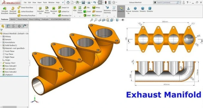
GD&T funciona de forma muy clara. Todo el proceso comienza con la creación del diseño. Como saben, los diseñadores utilizan software para crear modelos 3D. Durante esta fase, cuentan con la ayuda de GD&T, que se asegura de que cada detalle cumpla con las especificaciones requeridas. Verifican que el tamaño, la posición y la tolerancia cumplan con el estándar.
Tras añadir la especificación GD&T, el modelo deja de ser un simple modelo para convertirse en un conjunto completo de instrucciones para la producción. En este punto, la selección de los datos de referencia es crucial, ya que servirán como puntos, superficies o ejes de referencia para medir con precisión todas las demás características. Este es el paso clave que definirá los ensamblajes funcionales.

Básicamente, GD&T define la variación aceptable con respecto a la referencia. Este margen de tolerancia no compromete el ajuste, la calidad ni la funcionalidad de la pieza. Si se aplica la tolerancia correcta, la pieza no estará sobremecanizada ni holgada. Esto ahorra tiempo y ayuda a reducir el desperdicio.
Tras la producción, se utiliza GD&T para inspeccionar la calidad de la pieza final. Para ello, se emplean diferentes tipos de herramientas, como máquinas CMM, escáneres láser y calibradores. Después de todos estos pasos, GD&T sigue siendo útil, ya que facilita la comunicación entre diseñadores, ingenieros y fabricantes.
Errores comunes y buenas prácticas
Ya sabes, incluso un ingeniero experimentado puede cometer errores. Pero si sabes cuáles son esos errores y cómo evitarlos, las probabilidades de equivocarse serán mínimas. Echa un vistazo;
Errores comunes
- Dibujos excesivamente complicados: El uso excesivo de símbolos y tolerancias innecesarias puede resultar confuso para los fabricantes y ralentizar la producción.
- Selección incorrecta del dato: Ya sabes, elegir la referencia correcta es necesario; de lo contrario, arruinará todo el juego.
- Ignorando los requisitos de la función: Algunas personas solo se fijan en la apariencia de la pieza, pero el rendimiento es lo que más importa. Por lo tanto, aplique la tolerancia geométrica con cuidado.

Mejores prácticas:
- No compliques las cosas: Intenta usar solo los símbolos necesarios. No los sobrecargues. De lo contrario, será difícil de entender.
- Elija el dato con prudencia.Los puntos de referencia determinan las dimensiones de la pieza final. Por lo tanto, elija con cuidado.
- Comunícate con tu equipoPara confirmar las tolerancias y hacerlas alcanzables y prácticas, comuníquese con los equipos de fabricación y calidad durante la fase de diseño.
Bueno, al evitar los errores descritos anteriormente y seguir las mejores prácticas, puede fabricar piezas de calidad, reducir el retrabajo y aumentar la eficiencia de nuestro trabajo. Por lo tanto, podemos decir que hay un número ilimitado de posibilidades. beneficios de GD&T si sigues las reglas correctamente.
Resumen y conclusión
De acuerdo. Podemos concluir, a partir de lo anterior, que para la creación de piezas precisas y exactas, el GD&T es vital en la fabricación moderna. Ayuda a definir la tolerancia, la forma, el tamaño y la posición. Además, facilita la comunicación entre el equipo. En definitiva, ayuda a reducir errores y ahorra tiempo y dinero.