Tabla de referencia de comandos de código G
- Por: HDCMFG
El código G (código geométrico) es el lenguaje de programación universal utilizado para controlar máquinas CNC (control numérico por computadora). Desarrollado en la década de 1950 en el MIT, el código G sigue siendo la piedra angular del mecanizado CNC moderno, permitiendo un control preciso de procesos como el fresado, el torneado y el corte por láser.
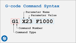
Cada comando de código G comienza con una letra (por ejemplo, G, M o F) seguida de valores numéricos, que indican a la máquina que debe:
- Controlar el movimiento (comandos G):Determinar la trayectoria y la velocidad de la herramienta (por ejemplo, movimiento a coordenadas, movimiento lineal/de arco).
- Administrar funciones (comandos M): Manejar acciones de inicio/parada (por ejemplo, rotación del husillo, cambios de herramienta, encendido/apagado del refrigerante).
Aunque está estandarizado según la norma ISO 6983, existen variaciones entre los fabricantes de máquinas (p. ej., Fanuc, Haas, Siemens). Esta tabla abarca el código G 90% de propósito general. Para funciones avanzadas (5 ejes, macros), consulte siempre el manual de su máquina para comprobar la compatibilidad.
Conceptos clave:
- Comandos modales: Permanecer activo hasta que sea reemplazado (por ejemplo,
G01permanece en modo de movimiento lineal). - Comandos no modales:Ejecutar una vez (por ejemplo,
G28vuelve a la posición inicial). - Unidades:
G20(pulgadas) /G21(milímetros). - Sistemas de coordenadas:
G54–G59(compensaciones de trabajo),G90(posicionamiento absoluto),G91(posicionamiento incremental). - Ejecución secuencial: La máquina lee el código línea por línea, de arriba a abajo, Sin saltos ni bucles a menos que utilice funciones avanzadas
Categorías de código G
| Categoría | Comandos de ejemplo | Función primaria |
|---|---|---|
| Control de movimiento | G00, G01, G02, G03 | Movimiento de la herramienta (rápido/lineal/arco) |
| Selección de plano | G17, G18, G19 | Seleccionar plano de trabajo (XY/XZ/YZ) |
| Unidades y medidas | G20 (pulgadas), G21 (mm) | Establecer sistema de medición |
| Sistemas de coordenadas | G54-G59, G92 | Definir desplazamientos de trabajo o coordenadas temporales |
| Compensación de herramientas | G40, G41, G42, G43 | Ajuste el tamaño/longitud de la herramienta |
| Ciclos enlatados | G81-G89 | Rutinas automatizadas de taladrado y roscado |
| Control del husillo | M03, M04, M05 | Iniciar/detener la rotación del husillo |
| Control de refrigerante | M08, M09 | Encender/apagar el refrigerante |
| Control de programas | M30, M02 | Finalizar programa/reiniciar máquina |
| Funciones especiales | G28, G53 | Regresar a las coordenadas de inicio/máquina |
Nota: El 80% de los programas básicos utiliza únicamente: G00/G01, G17/G20/G21, M03/M05, y M30.
Tabla de referencia de comandos de código G común
| Dominio | Función | Parámetros | Ejemplo | Notas |
|---|---|---|---|---|
| G00 | Posicionamiento rápido (movimiento sin corte) | X, Y, Z (coordenadas del objetivo) | G00 X10 Y5 Z2 | Evite colisiones, no se producen cortes. |
| G01 | Interpolación lineal (movimiento de corte) | X, Y, Z, F (velocidad de avance) | G01 X20 Y15 Z0 F150 | Mantener una velocidad de alimentación constante para el acabado de la superficie. |
| G02 | Interpolación circular en sentido horario | X, Y, I, J, K (desplazamientos del centro del arco) | G02 X30 Y30 I5 J0 | I/J/K definen el centro del arco en relación con el punto de inicio. |
| G03 | Interpolación circular en sentido antihorario | Igual que G02 | G03 X40 Y20 I0 J-5 | Se utiliza para arcos y círculos. |
| G17 | Selección del plano XY | Ninguno | G17 | Plano predeterminado para la mayoría de operaciones de fresado. |
| G18 | Selección del plano XZ | Ninguno | G18 | Se utiliza para operaciones de torno. |
| G19 | Selección del plano YZ | Ninguno | G19 | Rara vez se utiliza en fresado estándar. |
| G20 | Unidades en pulgadas | Ninguno | G20 | Establece todos los valores en pulgadas. |
| G21 | Unidades metricas | Ninguno | G21 | Establece todos los valores en milímetros. |
| G28 | Regresar a la posición inicial | X, Y, Z (opcional mediante intermedio) | G28 X0 Y0 Z0 | La máquina se mueve al punto de referencia. |
| G40 | Cancelar compensación de corte | Ninguno | G40 | Desactiva el desplazamiento del radio de la herramienta. |
| G41 | Compensación del cortador izquierdo | D (número de compensación del radio de la herramienta) | G41 D1 | Compensa el radio de la herramienta a la izquierda de la trayectoria. |
| G42 | Compensación del cortador derecho | D (número de compensación del radio de la herramienta) | G42 D2 | Compensa el radio de la herramienta a la derecha de la trayectoria. |
| G43 | Compensación de longitud de herramienta | H (número de compensación de altura de la herramienta) | G43 H3 | Se ajusta a la longitud de la herramienta; fundamental para configuraciones de múltiples herramientas. |
| G54 | Sistema de coordenadas de trabajo 1 | Ninguno | G54 | Selecciona el desplazamiento de trabajo predefinido (G54–G59). |
| G80 | Cancelar modos de movimiento | Ninguno | G80 | Cancela ciclos (por ejemplo, taladrado, roscado). |
| G90 | Posicionamiento absoluto | Ninguno | G90 | Todas las coordenadas son relativas al origen. |
| G91 | Posicionamiento incremental | Ninguno | G91 | Las coordenadas son relativas a la posición actual. |
| M03 | Inicio del husillo (en sentido horario) | S (velocidad del husillo) | M03 S2000 | El husillo gira en el sentido de las agujas del reloj a 2000 RPM. |
| M04 | Arranque del husillo (en sentido contrario a las agujas del reloj) | S (velocidad del husillo) | M04 S1500 | Se utiliza para operaciones de corte inverso. |
| M05 | Tope del husillo | Ninguno | M05 | Detiene el husillo después de la operación. |
| M06 | Cambio de herramienta | T (número de herramienta) | M06 T5 | Cambio automático de herramienta (requiere ATC). |
| M08 | Refrigerante encendido | Ninguno | M08 | Activa el refrigerante de inundación. |
| M09 | Refrigerante apagado | Ninguno | M09 | Apaga el refrigerante. |
| M30 | Fin y reinicio del programa | Ninguno | M30 | Finaliza el programa y reinicia la máquina. |
| F | Velocidad de alimentación | Valor de alimentación (unidades/min o unidades/rev) | F200 | Establecer en G94 (unidades/min) o G95 (unidades/rev). |
| S | Velocidad del husillo | Valor de RPM | S3000 | La velocidad depende del material y del tipo de herramienta. |
| T | Selección de herramientas | Número de herramienta | T4 | Prepara la herramienta para el comando M06. |
Preguntas más frecuentes
¿Necesito memorizar todos los códigos G?
No. El software CAM moderno genera la mayor parte del código automáticamente. Concéntrese en comprender comandos comunes como G00, G01, M03, y M30.
¿Los códigos G son los mismos para todas las máquinas?
Las funciones básicas son universales, pero las avanzadas varían según la marca. Por ejemplo:
- Haas: G187 (modo de alta velocidad)
- Fanuc: G05.1 (suavizado)
Consulte siempre el manual de su máquina para obtener información específica.
¿Puede un código G incorrecto dañar la máquina?
Sí. Por ejemplo:
Usando G00 (movimiento rápido) en lugar de G01 (corte lento) → La herramienta choca contra la pieza de trabajo.
Olvidando M05 (parada del husillo) → El husillo continúa girando después de que finaliza el programa.
¿Cómo utilizar el código G de forma segura?
- Prueba primero: ejecuta los programas en modo de “ejecución en seco” (sin cortes).
- Modo de bloque único: ejecuta una línea a la vez para detectar errores.
- Configuración de copia de seguridad: anote las compensaciones de la máquina antes de editar.
- Limpiar el espacio de trabajo: eliminar los residuos que puedan interferir con el movimiento.
¿Puedo editar el código G manualmente?
Sí, pero solo ajuste los valores que comprenda completamente y nunca modifique las trayectorias de las herramientas sin el software CAM: pequeños errores pueden provocar fallas.
¿Qué software crea código G?
Programas CAM: Fusion 360, Mastercam, SolidWorks CAM (de pago), FreeCAD, Easel (basado en web).
Nota: Evite escribir código desde cero a menos que tenga experiencia.
Recursos
- Documentación del código G de LinuxCNC
- Manual de programación de la serie Fanuc 30i/31i/32i
- Guía de programación avanzada de Siemens 840D SL
- Norma ISO 6983-1
- Manual de programación de Haas Mill
- Manual de programación CNC Mazak SmoothX
- Fundamentos del código G (NRAO)
- Blog de recetas de CNC
- Visor de NC (Web, gratuito)
- CAMotics (código abierto)
- Vericut
- Maquinista práctico
- Foro LinuxCNC
- Stack Exchange – Fabricación
- Reddit r/CNC