Справочная таблица команд G-кода
- К: HDCMFG
G-код (геометрический код) — универсальный язык программирования, используемый для управления станками с ЧПУ (числовым программным управлением). Разработанный в 1950-х годах в Массачусетском технологическом институте, G-код остается основой современной обработки с ЧПУ, обеспечивая точный контроль над процессами обработки, такими как фрезерование, точение и лазерная резка.
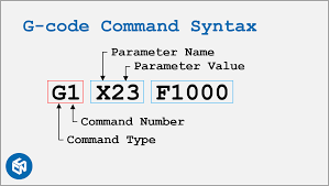
Каждая команда G-кода начинается с буквы (например, G, M или F), за которой следуют числовые значения, указывающие машине:
- Управление движением (G-команды): Определите траекторию и скорость инструмента (например, перемещение по координатам, линейное/дуговое движение).
- Управление функциями (M-команды): Управление действиями запуска/остановки (например, вращение шпинделя, смена инструмента, включение/выключение подачи охлаждающей жидкости).
Хотя они стандартизированы по ISO 6983, существуют различия между производителями станков (например, Fanuc, Haas, Siemens). Эта таблица охватывает 90% G-кодов общего назначения. Для получения информации о расширенных функциях (5 осей, макросы) всегда проверяйте совместимость с руководством по эксплуатации вашего станка.
Ключевые концепции:
- Модальные команды: Остаются активными до замены (например,
Г01остается в режиме линейного движения). - Немодальные команды: Выполнить один раз (например,
Г28возвращается в исходное положение). - Единицы:
G20(дюймы) /Г21(миллиметры). - Системы координат:
Г54–Г59(рабочие зачеты),Г90(абсолютное позиционирование),Г91(инкрементальное позиционирование). - Последовательное выполнение: Машина считывает код строка за строкой, сверху вниз, Никаких пропусков и зацикливаний если не используются расширенные функции
Категории G-кода
| Категория | Примеры команд | Основная функция |
|---|---|---|
| Управление движением | Г00, Г01, Г02, Г03 | Движение инструмента (быстрое/линейное/дуговое) |
| Выбор самолета | Г17, Г18, Г19 | Выберите рабочую плоскость (XY/XZ/YZ) |
| Единицы и измерения | G20 (дюймы), G21 (мм) | Установить систему измерения |
| Системы координат | Г54-Г59, Г92 | Определить рабочие смещения или временные координаты |
| Компенсация инструмента | Г40, Г41, Г42, Г43 | Отрегулируйте размер/длину инструмента |
| Консервированные циклы | Г81-Г89 | Автоматизированные процедуры сверления/нарезания резьбы |
| Управление шпинделем | М03, М04, М05 | Запуск/остановка вращения шпинделя |
| Управление охлаждающей жидкостью | М08, М09 | Включить/выключить охлаждающую жидкость |
| Управление программой | М30, М02 | Завершить программу/сбросить настройки машины |
| Специальные функции | Г28, Г53 | Вернуться к домашним/машинным координатам |
Примечание: 80% базовых программ используют только: Г00/Г01, Г17/Г20/Г21, М03/М05, а также М30.
Таблица ссылок на общие команды G-кода
| Команда | Функция | Параметры | Пример | Примечания |
|---|---|---|---|---|
| Г00 | Быстрое позиционирование (перемещение без резки) | X, Y, Z (координаты цели) | G00 X10 Y5 Z2 | Избегайте столкновений, никаких срезов не происходит. |
| Г01 | Линейная интерполяция (режущий ход) | X, Y, Z, F (скорость подачи) | G01 X20 Y15 Z0 F150 | Поддерживайте постоянную скорость подачи для получения качественной поверхности. |
| Г02 | Круговая интерполяция по часовой стрелке | X, Y, I, J, K (смещения центра дуги) | G02 X30 Y30 I5 J0 | I/J/K определяют центр дуги относительно начальной точки. |
| Г03 | Круговая интерполяция против часовой стрелки | То же, что и G02 | G03 X40 Y20 I0 J-5 | Используется для дуг и окружностей. |
| Г17 | Выбор плоскости XY | Никто | Г17 | Плоскость по умолчанию для большинства фрезерных операций. |
| Г18 | Выбор плоскости XZ | Никто | Г18 | Используется для токарных работ. |
| Г19 | Выбор самолета YZ | Никто | Г19 | Редко используется при стандартном фрезеровании. |
| G20 | Дюймовые единицы | Никто | G20 | Устанавливает все значения в дюймах. |
| Г21 | Метрические единицы | Никто | Г21 | Устанавливает все значения в миллиметрах. |
| Г28 | Возврат в исходное положение | X, Y, Z (опционально через промежуточный) | G28 X0 Y0 Z0 | Машина движется к контрольной точке. |
| Г40 | Отменить компенсацию резака | Никто | Г40 | Отключает смещение радиуса инструмента. |
| Г41 | Компенсация левого резака | D (номер смещения радиуса инструмента) | Г41 Д1 | Компенсирует радиус инструмента слева от траектории. |
| Г42 | Компенсация правого резака | D (номер смещения радиуса инструмента) | Г42 Д2 | Компенсирует радиус инструмента справа от траектории. |
| Г43 | Компенсация длины инструмента | H (номер смещения высоты инструмента) | Г43 Н3 | Регулируется по длине инструмента; критически важно для многоинструментальных установок. |
| Г54 | Рабочая система координат 1 | Никто | Г54 | Выбирает предопределенное смещение заготовки (G54–G59). |
| Г80 | Отменить режимы движения | Никто | Г80 | Отменяет циклы (например, сверление, нарезание резьбы). |
| Г90 | Абсолютное позиционирование | Никто | Г90 | Все координаты указаны относительно начала координат. |
| Г91 | Инкрементное позиционирование | Никто | Г91 | Координаты указаны относительно текущего положения. |
| М03 | Запуск шпинделя (по часовой стрелке) | S (скорость шпинделя) | М03 С2000 | Шпиндель вращается по часовой стрелке со скоростью 2000 об/мин. |
| М04 | Запуск шпинделя (против часовой стрелки) | S (скорость шпинделя) | М04 С1500 | Используется для операций обратной резки. |
| М05 | Остановка шпинделя | Никто | М05 | Останавливает шпиндель после работы. |
| М06 | Смена инструмента | Т (номер инструмента) | М06 Т5 | Автоматическая смена инструмента (требуется ATC). |
| М08 | Охлаждающая жидкость включена | Никто | М08 | Активирует подачу охлаждающей жидкости. |
| М09 | Охлаждающая жидкость выключена | Никто | М09 | Отключает охлаждающую жидкость. |
| М30 | Завершение программы и сброс | Никто | М30 | Завершает программу и сбрасывает настройки машины. |
| Ф | Скорость подачи | Подача (ед./мин. или ед./об.) | Ф200 | Устанавливается в G94 (ед./мин) или G95 (ед./об). |
| С | Скорость шпинделя | Значение оборотов в минуту | С3000 | Скорость зависит от материала и типа инструмента. |
| Т | Выбор инструмента | Номер инструмента | Т4 | Подготавливает инструмент для команды M06. |
Часто задаваемые вопросы
Нужно ли мне запоминать все G-коды?
Нет. Современное программное обеспечение CAM генерирует большую часть кода автоматически. Сосредоточьтесь на понимании общих команд, таких как Г00, Г01, М03, а также М30.
G-коды одинаковы для всех станков?
Базовые функции универсальны, но расширенные функции различаются в зависимости от бренда. Например:
- Haas: G187 (высокоскоростной режим)
- Fanuc: G05.1 (сглаживание)
Всегда проверяйте подробную информацию в руководстве по эксплуатации вашего устройства.
Может ли неправильный G-код повредить машину?
Да. Например:
С использованием Г00 (быстрый ход) вместо Г01 (медленная резка) → Инструмент врезается в заготовку.
Забывая М05 (остановка шпинделя) → Вертушка продолжает вращаться после завершения программы.
Как безопасно использовать G-код?
- Сначала проведите тестирование: запустите программы в режиме "пробного запуска" (без вырезания фрагментов).
- Режим одиночного блока: выполнение одной строки за раз для выявления ошибок.
- Настройки резервного копирования: запишите смещения машины перед редактированием.
- Очистите рабочее место: уберите мусор, который может мешать движению.
Могу ли я редактировать G-код вручную?
Да, но изменяйте только те значения, которые вы полностью понимаете, и никогда не изменяйте траектории инструмента без программного обеспечения CAM — небольшие ошибки могут привести к сбоям.
Какое программное обеспечение создает G-код?
Программы CAM: Fusion 360, Mastercam, SolidWorks CAM (платная), FreeCAD, Easel (веб-версия).
Примечание: Избегайте написания кода с нуля, если у вас нет опыта.
Ресурсы
- Документация LinuxCNC G-Code
- Руководство по программированию серий Fanuc 30i/31i/32i
- Siemens 840D SL Расширенное руководство по программированию
- Стандарт ИСО 6983-1
- Рабочая тетрадь по программированию Haas Mill
- Руководство по программированию станков с ЧПУ Mazak SmoothX
- Основы G-кода (NRAO)
- Блог кулинарной книги CNC
- NC Viewer (веб, бесплатно)
- CAMotics (с открытым исходным кодом)
- Верикат
- Практический машинист
- Форум LinuxCNC
- Stack Exchange – Производство
- Reddit r/CNC