Casting shrinkage sounds like a simple idea—metal gets smaller as it cools. But in real production, casting shrinkage is one of the main reasons parts end up with internal voids, surface depressions, leaks in pressure-tested components, or “surprise scrap” after CNC machining. The tricky part is that shrinkage isn’t just one event. It happens across stages of cooling and solidification, and whether it becomes a casting defect depends on whether the casting can be “fed” with liquid metal as it freezes.
This article walks through what casting shrinkage is, the difference between normal shrinkage and shrinkage defects, why hot spots matter, and the practical prevention strategies that make machining easier and quality more predictable.
What Is Casting Shrinkage?
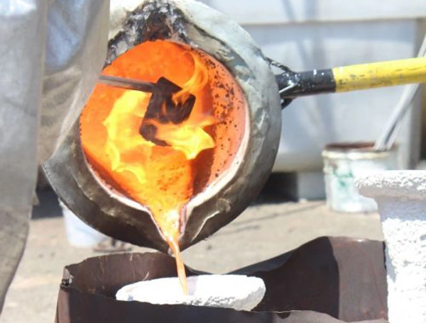
Casting shrinkage is the natural volume reduction that occurs as molten metal cools and transforms into a solid casting. In every alloy system, the metal contracts as temperature drops, and it also contracts during the liquid-to-solid transition.
Shrinkage becomes a defect only when the casting cannot pull in enough liquid metal during freezing to make up for that volume loss. When feeding is insufficient, the result can be a visible cavity, or it can be a network of small voids hidden inside the part that only appears during inspection or machining.
Types of Shrinkage in Casting
Shrinkage is usually discussed in three stages because each stage influences the process differently. The first is liquid shrinkage, which happens while the metal is still fully liquid and cooling down. The second is solidification shrinkage, which occurs as metal transitions from liquid to solid—this is the stage most directly tied to shrinkage cavities and shrinkage porosity. The third is solid-state shrinkage, which happens after the casting is already solid and continues cooling to room temperature.
In practical terms, when people talk about “shrinkage defects,” they’re almost always talking about what happens during solidification, because that’s when the casting needs a continuous supply path for liquid metal.
How does Shrinkage Defect Appear in Different Casting Processes?
The “personality” of a shrinkage defect is heavily dictated by the mold’s ability to extract heat and the pressure applied during solidification. While the physics of cooling is constant, a sand mold and a water-cooled steel die create very different “internal landscapes” for the machinist to navigate.
Shrinkage Cavity vs Shrinkage Porosity
Shrinkage problems usually show up in one of two ways.
A shrinkage cavity is the more obvious form—a larger void that forms when a hot region solidifies last and there isn’t enough feed metal. A shrinkage porosity condition is more subtle. Instead of one large void, you get a sponge-like cluster of small voids distributed through a region, often in thicker sections or at hot spots. In radiographic standards for steel castings, shrinkage is commonly discussed in patterns like linear, feathery, and sponge-type shrinkage—because the “shape” of shrinkage tells you something about how feeding and solidification behaved.
Both forms are painful for different reasons. Cavities can cause immediate rejection. Porosity can pass early checks and then fail later when you machine into it or pressure test the part.
Why Hot Spots Create Shrinkage Defects
If you want one concept that explains most casting shrinkage issues, it’s this: hot spots freeze last.
A hot spot is a region with a high volume-to-surface-area ratio. It cools and solidifies more slowly than surrounding sections, so it becomes the last place to freeze. When that last region solidifies, it contracts. If liquid metal can’t reach it through still-open feeding paths, it leaves behind a cavity or porosity. This is why design and process teams focus so heavily on hot spots and directional solidification.
What Typically Causes Shrinkage Defects
Shrinkage defects don’t usually come from a single mistake. They come from a mismatch between solidification behavior and feeding ability.
A common cause is inadequate feeding design—meaning risers are too small, too far, or not placed to feed the final-freezing region. Another frequent cause is poor directional solidification, where multiple sections freeze in a way that traps liquid metal instead of pulling it toward a riser. Risers are meant to act as molten reservoirs and thermal “heat banks” so the casting freezes toward the riser and stays feedable as long as possible.
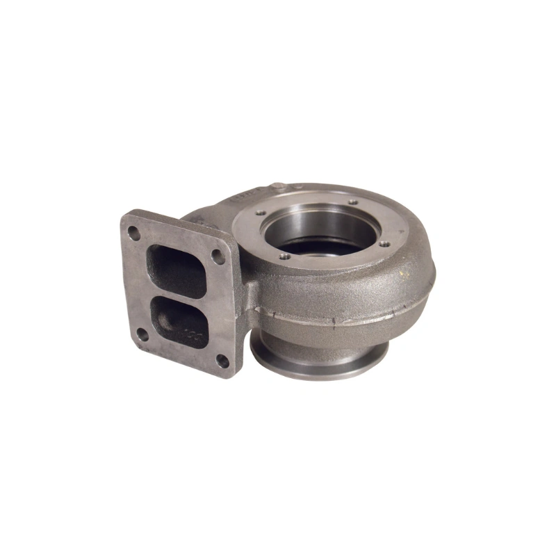
Geometry plays a major role too. Thick-to-thin transitions, isolated heavy bosses, and large junctions are classic shrinkage hot spots. Process variables also matter—pour temperature, pouring practice, mold material, and cooling conditions can all shift where the last-freezing region occurs and whether the feeding paths stay open long enough.
How to Prevent Casting Shrinkage Defects
The most reliable strategy is not “try harder at inspection.” It’s to engineer the freezing behavior so shrinkage is fed intentionally.
That usually starts by forcing directional solidification. You want the casting to freeze from the farthest points back toward the riser, so the last region to freeze is connected to a reservoir of liquid metal. This is where riser placement, riser size, and neck design matter, because the riser must stay liquid longer than the section it feeds.
Then you manage hot spots. Sometimes the best fix is design-related—smoother transitions, adding fillets, or reducing isolated mass. Sometimes the fix is process-related—using chills to pull heat out of a region so it freezes sooner, or adjusting gating so metal flow and temperature distribution are more favorable. In modern production, simulation is often used to identify hot spots and predict feeding problems before tooling is finalized, because shrinkage issues are cheaper to solve on a screen than on a machining center.
How Casting Shrinkage Shows Up During CNC Machining
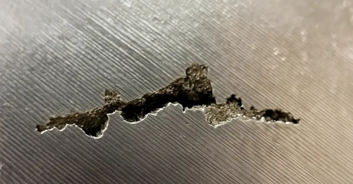
Shrinkage is one of the most common “everything looked fine until we machined it” problems.
You may see pores open up on sealing faces, threaded ports, or gasket surfaces. You may hit a cavity near a bore or seat, turning a nearly finished part into scrap. Even when voids aren’t exposed, shrinkage porosity can cause local surface tearing, inconsistent finishes, or leak paths in pressure-containing parts. That’s why shrinkage control is tightly connected to machining allowance and datum strategy: if the as-cast condition is unstable or porous in functional zones, you’re forced to leave more stock and do more rework to protect quality.
How Shrinkage Is Detected
Resources: Mat Research
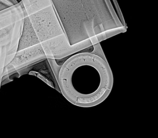
Surface cavities are easy to catch visually, but shrinkage porosity often requires inspection methods that can “see inside” the casting. Radiography is widely used to classify internal discontinuities, and reference radiograph standards explicitly categorize shrinkage patterns and severity levels for castings, which is why many industrial specs call out radiographic acceptance criteria.
The practical takeaway is simple: if a part is pressure-retaining or fatigue-sensitive, don’t rely on surface appearance alone. Align inspection expectations early so you don’t discover shrinkage after you’ve already paid for machining.
What to Communicate Early So Shrinkage Doesn’t Become a Surprise
Shrinkage prevention becomes easier when the manufacturing intent is clear from the start.
If a surface must seal, say so early. If a bore is a functional seat, say so early. If the part will be pressure tested, say so early. That lets the supplier protect those zones through feeding design, solidification control, and inspection planning. It also helps to clarify what will be machined and what will remain as-cast, because that defines where shrinkage risk is acceptable and where it is not.
FAQ: Casting Shrinkage
Why do shrinkage problems sometimes show up only after CNC machining?
Because the defect is often internal. The raw casting surface can look normal, but when machining opens a sealing face, port, bore, or seat, you expose a void network that wasn’t visible from the outside.
How can I tell if the porosity I’m seeing is shrinkage or gas porosity?
A quick practical clue is location and pattern. Shrinkage tends to appear near heavier sections, junctions, and “last-to-freeze” zones, often as clustered or sponge-like voids. Gas porosity is more likely to be rounder, more uniformly scattered, and tied to surface/flow conditions. If it’s critical, ask your supplier to confirm with inspection evidence rather than guessing from photos.
Which part features are most likely to create shrinkage hotspots?
Heavy bosses, thick-to-thin transitions, T-junctions, large fillets around thick masses, and isolated “lumps” of material are the usual suspects—basically anywhere heat gets trapped and the metal freezes last.
Will increasing pour temperature solve shrinkage defects?
Not reliably. Higher temperature can improve fill, but it can also increase the amount of feeding needed and make hotspots worse. Shrinkage is usually solved by better feeding and solidification control, not by simply pouring hotter.
Can shrinkage defects be repaired (weld/impregnation), and when is it acceptable?
Some parts can be repaired, but it depends on your application. Welding can introduce distortion and new stress, and impregnation may work for leak paths but won’t restore strength where voids matter. For pressure-retaining or fatigue-critical components, many buyers restrict repairs or require approval and documentation.
What should I include in my RFQ to reduce the risk of shrinkage-related scrap?
Mention any pressure testing, leak-tight surfaces, fatigue-critical zones, and which features are “must be sound” after machining (ports, sealing faces, bores, threads). Also clarify what will be machined vs left as-cast, because it tells the supplier where shrinkage cannot be tolerated.
If my part is pressure-retaining, what’s the smartest inspection approach to request?
Don’t rely on visual checks alone. Ask for an inspection plan that matches the risk: where internal soundness matters (around ports, sealing faces, thick junctions), request appropriate verification before heavy machining adds value. The exact method depends on material and geometry, but the intent should be “prove soundness in critical zones.”
How does casting shrinkage affect machining allowance and cost?
If shrinkage risk is high, you’re forced to leave more stock to guarantee cleanup and avoid opening voids—meaning longer CNC cycle times and more scrap risk late in the process. A stable feeding design and sound casting lets you reduce machining allowance and machine more confidently.
What’s the fastest “fix” if shrinkage keeps recurring on the same part?
Treat it as a repeatable root cause: the last-freezing zone isn’t being fed consistently. The fastest path is usually reviewing hotspot locations (especially around thick sections and junctions), then updating feeding/solidification controls—not just sorting parts harder after the fact.
Conclusion
Casting shrinkage is unavoidable—but shrinkage defects are not. When the freezing pattern is engineered correctly and the casting stays feedable until the last hot spot solidifies, shrinkage is compensated instead of trapped inside the part. The payoff shows up where it matters: fewer leaks, fewer surprises during CNC machining, more stable tolerances, and lower total cost.
If shrinkage has been a recurring issue on similar parts, it’s usually worth addressing it early—at the design and process-planning stage—because it’s far cheaper than discovering voids after machining has already added value.