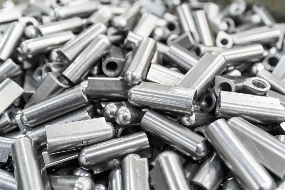
Close die forging has found a lot of applications in modern manufacturing. You can see its outcomes in high-strength components across automotive, aerospace, and industrial sectors. You place a heated metal billet between two or more dies, and shape metal using extreme pressure and precision tooling. Specifically, these dies contain the negative profile of the required component. The extreme force or pressure forces the metal to fill the die cavity completely. Consequently, the process creates a part with better mechanical properties.
Metallurgists and engineers prefer this method because it aligns the internal grain structure of the metal. In contrast, castings often have random grain structures, whereas machining cuts through the grain flow. Close die forging makes the grain follow the shape of the part. This continuous grain flow results in excellent strength that resists fatigue, and you get parts that can withstand high stress and cyclic loads.
The Mechanics of Closed Die Forging
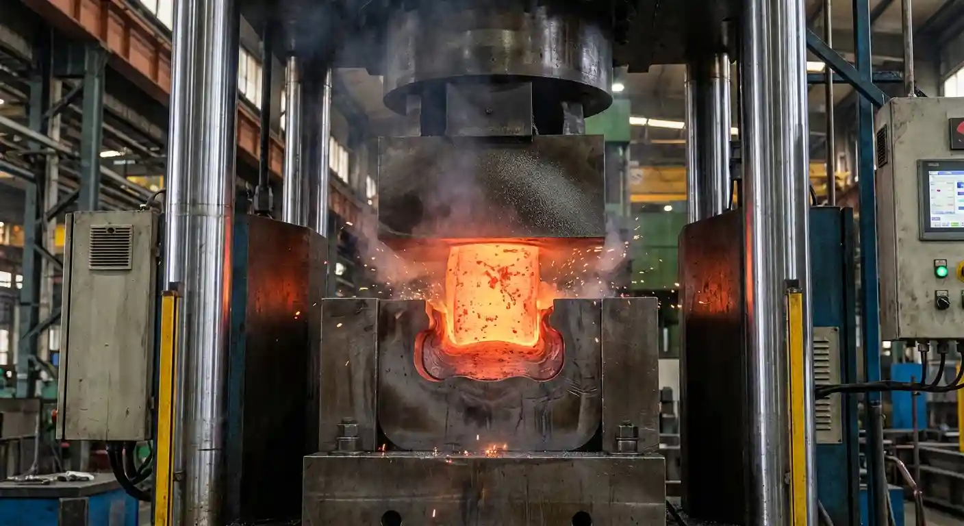
The closed die forging uses the plastic deformation property of the metal. To begin, you heat a metal workpiece to a temperature where it becomes malleable. Then, you place this workpiece on a stationary bottom die, and a moving top die drops to strike and press the metal. The force causes the material to flow into the designated shape.
This process differs from open die forging, which uses flat or simple dies. Typically, it requires the operator to manually manipulate the workpiece. However, the close die forging encloses the metal, and the dies restrict the flow of material in all directions except where the negative profile of the die allows. This restriction ensures the metal fills every detail of the die cavity.
Pressure plays an important role. The pressing equipment must deliver enough force to overcome the yield strength of the material. However, as the metal cools, its yield strength increases. The machinery must have the ability to maintain pressure on the cooling metal to complete the shape. You can achieve near-net shapes with this method, which reduces the need for extensive machining later.
Role of Flash in Forging
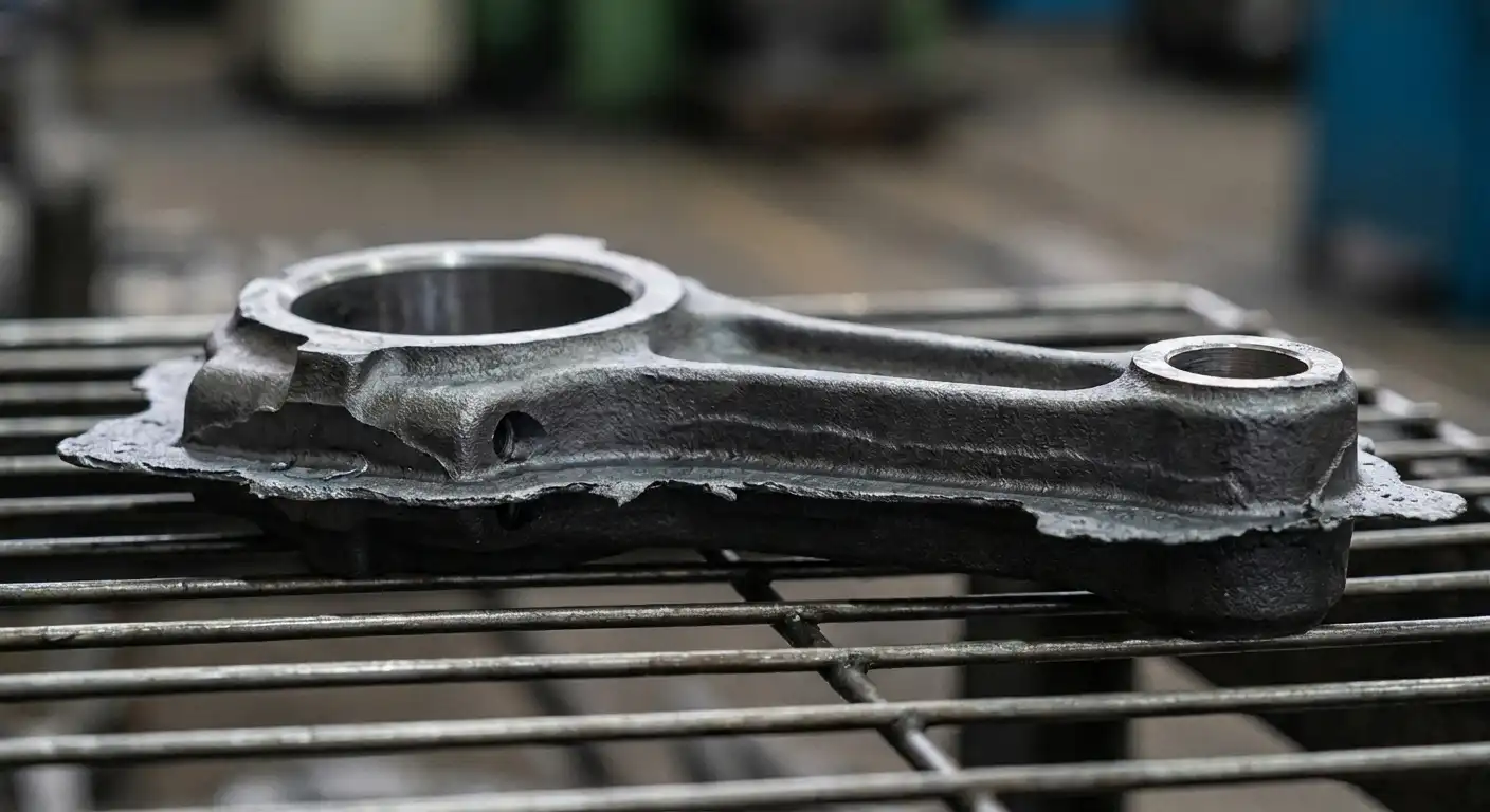
Flash is the excess material that leaks out between the two halves of the die. You may consider flash to be a waste, but experienced forgers know it serves a critical function. We call the gap between dies the flash land. As the metal flows outward, it enters this narrow channel.
The metal cools fast in the flash land, leading to an increase in the strength of the material in that area. This hardened ring of metal creates a pressure barrier and prevents more metal from flowing out, leading to pressure buildup inside the die cavity. This increased pressure forces the remaining hot metal to fill difficult spaces and sharp corners.
Without flash, you may end up filling the die incompletely, resulting in a part that lacks definition. After the forging stroke ends, you remove the flash. Later, a trimming process cuts away this extra material. The amount of flash depends on the volume of the billet used, and accurate volume calculations help in minimizing the waste.
Step by Step Manufacturing Process
A good forging process calls for a strict sequence. You need to follow these steps to make sure there is a quality and consistency in the resulting part.
Billet Preparation
First, you start the process with a metal bar or billet, and saws or shears help cut the billet to a precise weight and length. The volume of the starting piece is equal the volume of the completed part as well as the excess flash. Accurate cutting helps prevent waste of the material and die damage.
Heating
Furnaces increase the temperature of the billet, and the target temperature depends on the alloy. Steel needs temperatures around 1100 degrees Celsius to 1250 degrees Celsius, whereas Aluminum requires lower ranges. Now a days, induction heating systems provide uniform heat faster, but the gas furnaces offer an alternative for larger batches. The more uniform the heating is the more consistent the plastic deformation will be.
Descaling
Heated steel reacts with oxygen and forms a layer of iron oxide scale on the surface. You must remove this scale before forging. If scale enters the die, it destroys the surface finish. Now a days, specialized mechanical devices or high-pressure water jets scrape the scale off.
Blocking
Complex shapes frequently require more than one hitting. The first hit occurs in a blocker die, which distributes the metal roughly into the final shape and prepares the material for the finishing cavity. Blocking extends the life of the finishing die.
Finish Forging
Next, you transfer the rough part to the finish die, and the hammer or press hits the final blow. The metal fills the cavity completely and the excess material flows into the flash gutter. Now the part is in its final shape dimensions.
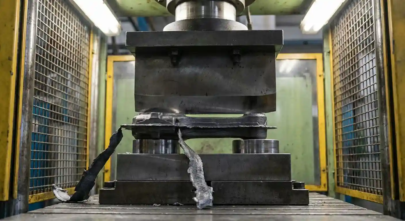
Trimming
Now, the part leaves the forge with the flash attached. A trimming press cuts the flash away from the main part. The key is to perform this while the part is still hot or after it leads to room temperature. After this the flash goes to recycling.
Cooling
Similarly, the controlled cooling prevents internal stress. You place the parts in bins or on conveyors. Some alloys require slow cooling in insulated pits, while others require air cooling. Most importantly, the cooling rate affects the hardness and microstructure.
Heat Treatment
Forging introduces stress and alters the grain structure. Heat treatment helps restore the desired properties, whereas, normalizing refines the grain. Whereas quenching and tempering increase hardness and strength. You need to choose the treatment based on the application requirements.
Surface Finishing
Finally, the last step involves cleaning the surface. Shot blasting removes remaining scale and discoloration. This creates a uniform matte finish. You inspect the parts for defects before shipment.
Forging Equipment and Machinery
You select equipment based on the part size, material, and production volume.
Drop Hammers
Drop hammers use gravity, where a heavy ram lifts and falls onto the workpiece. The energy of the drop depends on the weight of the ram and the drop height. Hammers help in delivering high-impact energy. This impact first deforms the surface, while the center of the workpiece deforms later. You may use hammers for small to medium parts. Although they offer versatility but at the same time, create significant noise and vibration.
Power Hammers
Likewise, in power hammers, steam or compressed air accelerates the ram to increase the striking energy. You have the ability to control the force of each blow. These machines suit high-volume production. They provide faster cycle times than gravity hammers.
Mechanical Presses
In mechanical presses, a flywheel and crank mechanism are used. The ram moves at a fixed speed and stroke length. The press delivers maximum force at the bottom of the stroke. You use mechanical presses for precision forging. They offer high production rates and automation potential. The squeezing action deforms the entire cross-section of the workpiece simultaneously.
Hydraulic Presses
Fluid pressure drives hydraulic presses. These machines deliver constant force throughout the stroke. You can control the speed and pressure. Hydraulic presses are good at forging large parts. They create deep impressions, but the cycle time is slower thanthat of mechanical presses. However, the versatility justifies the speed trade-off.
Screw Presses
Here, a large screw drives the ram. The screw converts rotational energy into linear force. Screw presses offer a balance between hammers and hydraulic presses. They provide high energy with controlled velocity. They are suitable for forging turbine blades and medical implants.
Tooling and Die Materials
The life of the die determines the economic viability of this process. Dies face extreme thermal and mechanical shock. Therefore, you always want materials that are capable of withstanding these conditions.
Tool Steels
H13 hot work tool steel is the industry standard. It contains chromium, molybdenum, and vanadium. This alloy is good at resisting thermal fatigue and cracking, and it helps maintain hardness at high temperatures. You harden and temper the dies to specific Rockwell C values.
Die Block Manufacturing
You engrave the die cavities using CNC milling or electrical discharge machining (EDM). In CNC milling, high-speed machining cuts the hardened steel, whereas EDM uses sparks to erode the metal. Later, you polish the cavity surfaces to facilitate metal flow and part ejection.
Wear and Lubrication
Likewise, the friction wears down the die surfaces. Lubricants reduce friction and protect the die. For example, you spray graphite-based lubricants on the dies between cycles. The lubricant also acts as a thermal barrier, and prevents the die from overheating. Proper lubrication extends die life quite a bit.
Die Design Features
Designers include draft angles in the form of a small taper on vertical walls within the die cavity. It allows you to remove the part from the die. Vertical walls without draft cause the part to stick. Standard draft angles range from 3 to 7 degrees. You also include fillets and corner radii. Sharp corners create stress concentrations, leading to die cracking. Radii help the metal flow smoothly around corners.
Suitable Materials for Forging
You can use almost all metals in the forging process. However, you select the material based on the mechanical properties of the required component.
Carbon Steels
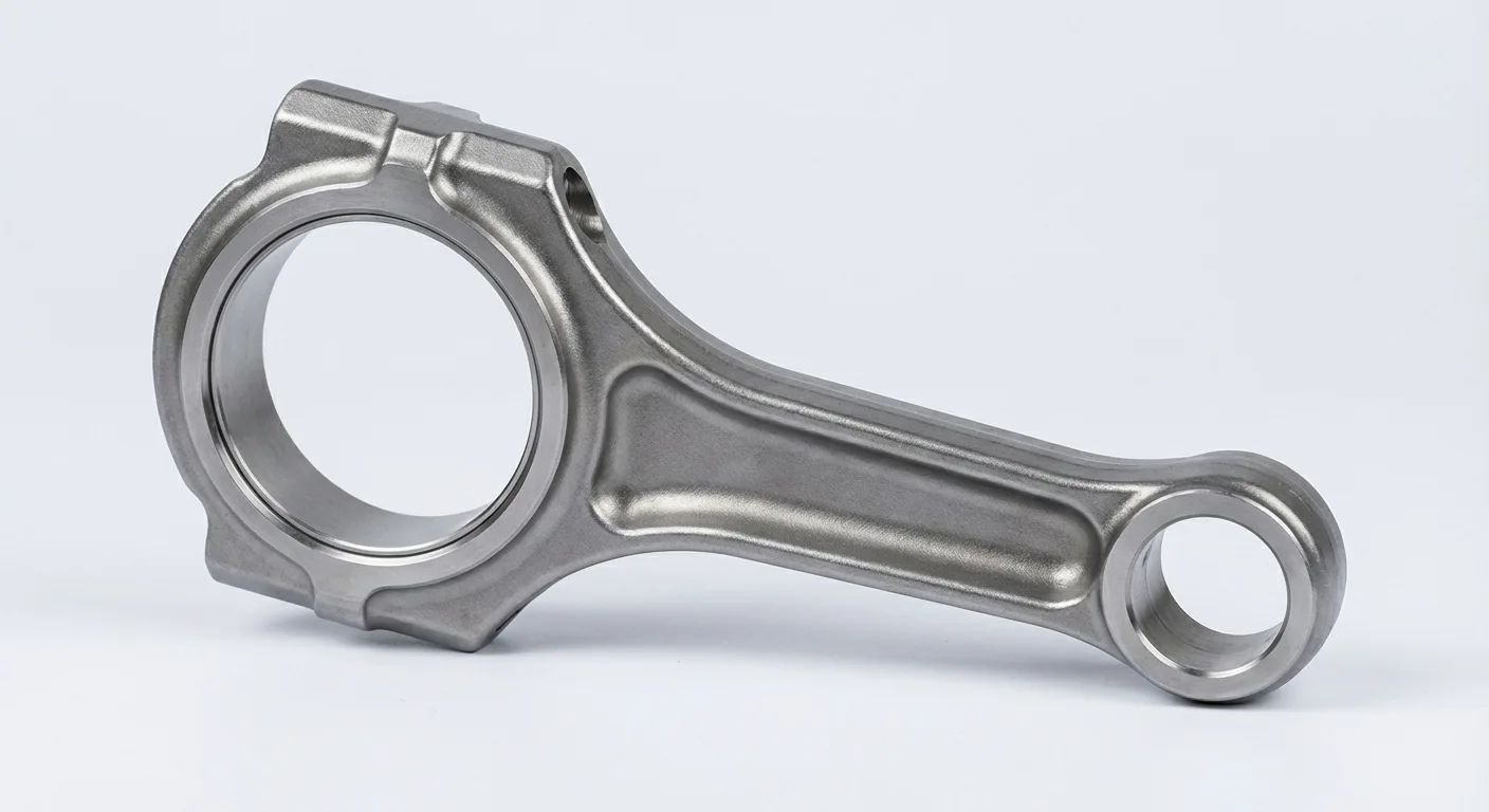
Forging industry uses carbon steels a lot, where grades like AISI 1045 and A105 offer a balance of strength and machinability. You use them for automotive connecting rods, crankshafts, and gears. They respond well to heat treatment.
Alloy Steels
Adding elements like chromium, nickel, and molybdenum enhances properties. Alloy steels like 4140 provide high toughness and wear resistance. You find these materials in heavy machinery and structural components. They can withstand larger loads than carbon steels.
Stainless Steels
Stainless steel is another common material due to its corrosion resistance property. Grades like 304 and 316 provide good resistance to rust and chemicals. However, forging stainless steel requires a higher force, and the material cools faster than carbon steel. Common uses include valves, fittings, and marine hardware.
Aluminium Alloys
Aluminum gives a high strength-to-weight ratio. Aerospace and automotive industries often need aluminum forgings. Alloys like 6061 and 7075 are common. Forging aluminum requires precise temperature control. Overheating causes the material to crumble, while underheating causes cracking.
Titanium Alloys
Titanium combines low weight with extreme strength and heat resistance. Aerospace engines and airframes utilize titanium forgings. This material is difficult to forge because it has a narrow temperature window. You require specialized lubricants and coatings. The cost is high, but performance justifies the expense.
Copper and Brass
Likewise, electrical conductivity and corrosion resistance make copper alloys highly attractive. You can forge brass for plumbing fittings and valves. These materials flow easily, hence causing less wear on the dies compared to steel.
Design Guidelines and Tolerances
Different factors need to be considered while designing for forging and machining. In both cases, you must account for the manufacturing limitations.
Parting Line Placement
The parting line is where the two halves of the die touch. Ideally, you place the parting line along a flat plane whenever possible to simplify die construction, because irregular parting lines increase cost. You position the line to balance the forces on the dies.
Ribs and Webs
Ribs are thin vertical projections, and webs are thin sections connecting thicker areas. Deep ribs are difficult to fill, but the thin webs cool quickly. You must design ribs with generous draft angles. You keep web thickness within practical limits to prevent cooling defects.
Machining Allowances
Forgings often do not come out as the finished product in a single step. Additional steps include flash removal and surface finish. To accommodate this, you purposefully add material to surfaces requiring machining. This extra material ensures you clean up the surface to the final dimension. Standard machining margins range from 1.5 millimeters to 3 millimeters depending on part dimensions.
Tolerances
Forging tolerances need to account for die wear, mismatch, and thermal expansion. International standards like ISO 2768 and other forging standards specify these values. Closer tolerances increase cost, and you balance the need for precision with the cost of production.
Common Defects and Quality Control
Defects compromise the structural integrity of the component. You must identify and prevent these defects at all costs.
Laps and Folds
A lap occurs when metal folds over itself, and the surfaces oxidize and fail to bond. This creates a crack-like defect. Poor die design or improper material distribution causes laps. This requires magnetic particle inspection to detect.
Cold Shuts
Two streams of metal meet but do not fuse together. This happens when either the metal is too cool or the pressure is insufficient. Consequently, cold shuts create weak points. Maintaining proper billet temperature helps in preventing this defect.
Underfill
The metal fails to fill the spaces within the die completely, resulting in missing features or rounded corners. Whereas, insufficient billet volume or trapped gases cause underfill. You can rectify this by increasing billet size or adding vent holes.
Scale Pits
Scale embedded in the surface creates pits. These pits remain after machining if they are deep enough. Proper descaling techniques alleviate this problem.
Die Shift
Misalignment between the two halves of the die causes die shift. Regular equipment maintenance checks are key in detecting and thus fixing die shift.
Inspection Methods
Visual inspection catches obvious surface defects. Dimensional inspection ensures the part meets print specifications. Non-destructive testing (NDT) such as Ultrasonic testing detects internal voids, and the magnetic particle inspection reveals surface cracks.
Economic Considerations
Forging offers economic benefits for bulk production.
Tooling Costs
Die sets account for an important upfront investment. You pay for the steel and the machining time. As a result, this cost makes forging expensive for small runs. You need a minimum quantity to recover the tooling cost.
Unit Costs
The material utilization in forging is high, where you waste less material than in machining from a block. The cycle time is fast. Combined, these factors reduce the per-unit cost. As volume increases, the savings compensate for the initial tooling investment.
Machining Savings
Forged parts resemble the final shape. This reduces the time spent on machining. You remove less material. This saves on labor and tool wear. The total cost of the finished part drops quite a bit.
Lead Times
Building dies takes time, and you must plan for this lead time. Once the dies are ready, production is fast. You need to keep backup dies to avoid downtime during repairs.
Comparing Forging Methods
Understanding the alternatives help you in selecting the right method for your component.
Close Die vs Open Die
Open die forging can accommodate massive components. It shapes metal roughly, so you can use it for shafts, rings, and blocks weighing tons. Whereas, close die forging can handle smaller, intricate parts. It provides better dimensional accuracy. You should choose open die for low volume and large size, while select close die for high volume and precision.
Close Die vs Casting
There are many types of casting processes, including sand casting, investment casting, and die casting, but their key principles are the same: pouring molten metal into a mold. which helps create complex internal cavities and shapes impossible to forge. However, castings have lower strength. They suffer from porosity, whereas, forging produces solid, dense parts. If strength is the priority, you should choose forging. If geometric complexity is important, you must select casting.
Close Die vs Machining
Machining involves cutting a part from a solid block. It gives the highest precision, and requires no tooling cost. However, it disrupts the grain flow, and wastes a lot of material. Therefore, machining is suitable for prototypes and low volumes, whereas forging is suitable for manufacturing high strength components.
Hot Forging vs Cold Forging
Hot forging shapes metal at high temperatures, making it easier to form large, complex parts with less press force. However, the cooling process leads to thermal shrinkage and surface scale, which reduces precision. In contrast, cold forging occurs at room temperature, which increases material strength through strain hardening and provides excellent dimensional accuracy. You should choose hot forging for massive, intricate components where high ductility is needed, while cold forging is ideal for high-volume, precise parts that require little to no secondary machining.
Future Trends in Forging
The forging industry is evolving, and the role of the automation technology is increasing. Robots handle hot billets, leading to improved safety and consistency. Simulation software reduces trial and error by allowing you to simulate the metal flow on a computer. This predicts defects before you even cut steel. Precision forging aims to eliminate machining as a whole. Net-shape forging produces ready-to-use parts.
Simultaneously, environmental concerns are there and they are the primary drivers of the change. Induction heating uses energy efficiently, while electric presses reduce oil consumption. The industry is trying to operate in a cleaner, leaner way.Conclusion
In conclusion, understanding close die forging helps you in making better manufacturing decisions. You balance cost, quality, and performance. This process remains the standard for producing structural components. Whether used in a car engine or an airplane wing, forged parts give the required reliability.
As a supplier covering metal parts manufacturing solutions from casting, forging, to CNC finishing, HDC Manufacturing is glad to offer help for your forging project in material selection, design optimization, and mold manufacturing. Feel free to contact us via email or phone.