Tired of spending your valuable time on designing a part and ending up with inaccurate results? DOn’t worry, you are not alone. Apparently, some parts may look perfect, but they can’t perform well, as they should. But here, in this blog. We have a solution to your problem. GD&T? Yes!
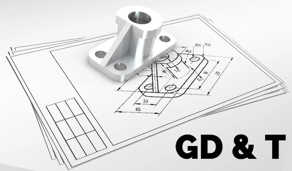
Geometric Dimensioning and Tolerancing is the language of precision that is accepted worldwide. This language ensures every part meets the required standard fully. So, let’s dive into detail!
History and Evolution of GD&T
We all know that old manufacturing was not very complex. It was just based on simple dimensions and blueprints. But after some time, the manufacturer felt that the products did not have the required precision. It was the stage when the story of GD&T took its start. After that, parts started to become more and more complex ( especially in the aircraft and automotive industries), and engineers felt that there was a lack of precision. Parts are not exactly fitting as they should be.
There was no fixed method of describing dimensions. Parameters were not pre-decided. This confusion compelled the introduction of Geometric Dimension and Tolerance (GD&T).
The origin of GD&T started in the 1940s. There was a British engineer, Stanley Parker, who gave the idea of “True Position”. His idea was appreciated! True position defines how a feature can deviate from its original position. In later years, this idea transformed into a complex system of geometric controls.

Let me tell you that GD&T was officially adopted by the U.S.military, MIL-STD-8, in the 1960s. After some time, organisations like ASME and ISO developed international standards. Due to this reason, GD&T has become a global language of precision. The idea is still evolving. It hasn’t stopped at a point. With the advent of new tools, they made changes according to modern manufacturing.
Now, it has become essential in every manufacturing site. The good thing is that due to CAD and digital inspection tools, understanding GD&T is not a big deal, now. Honestly, GD&T actually happened due to the demand for more accuracy, better communication, and fewer errors.
What is GD&T
GD&T stands for Geometric Dimensioning and Tolerancing. It is a system that defines dimensions and tolerance in a very clear and precise way. It guides the engineers, like how much deviation is acceptable, how much the part can vary from the exact dimensions and tolerance needed. We can say that this is the system that describes how perfect a part should be to function properly.
It doesn’t tell about the linear measurements only; it shows a feature in 3D space. Well, it controls the roundness, flatness, parallelism, and position of the part. Therefore, every part that will be manufactured by considering GD&T will fit perfectly and function properly, even if it’s made by different manufacturers.
Just take the example: You have to bake the cake. You know about the ingredients but not they way how to mix them, for a long time it should be baked. No doubt, you will end up messing it up. Likewise, before making a part, you should know about dimensioning and all that GD&T tells us.
If a part were not made with proper measurements, it would not align correctly. It will not perform well. Ultimately, it will waste your time and money. Therefore, if you want your parts to perform as you want them to, make them correctly, and make use of GD&T.
Why Use GD&T-Why it is important
GD&T improves accuracy, communication, and quality during manufacturing. It is not only a group of symbols; it helps manufacturers at every stage of operation. Have a look at why it is so important.
- Ensure precise communication: GD&T helps you understand every detail of the design very deeply. Everyone understands exactly what’s required, reducing the chances of mistakes.
- Defines functional tolerances: As we discussed, GD&T not only shows linear dimensions, it also shows what the part would look like when in 3D. For example, how flat, parallel, or round they must be. So, each part would be exactly according to the required specifications.
- Reduces manufacturing costs: As GD&T helps avoid over-tolerancing and under-tolerancing, it doesn’t make parts unnecessarily precise and allows too much variation. Well, due to the right balance, it saves material, time, and effort.
- Improves product quality and fit: As GD&T is a universal language, the part would have the same dimensions, even if it is manufactured by different designers.
Overall, we can say that GD&T is really helpful in designing, producing, an dinspecting parts that are accurate, functional, and reliable, doesn’t matter where they are being manufactured.
Basic Concepts and Terminology
If you don’t understand the basic terms of GD&T, you will not be able to design the part or even communicate properly with other designers. In this section, we will have a look at the basic terminologies you will often see in GD&T.
| Term | Meaning | Real Life Analogy |
| Feature | It is the actual part that you have to design | A car door’s handle or the hole where a bolt fits |
| Datum | A reference point, line, or surface used to measure or position other features | Just like a wall corner when hanging frames evenly on a wall |
| Tolearnce Zone | The acceptable zone within which a feature can vary and still function properly | Allowing a few millimetres of space when fitting a phone case |
| Feature Control Frame | A rectangular box having GD&T symbols, tolerance values, and datums | A specific chart describing how accurate a specific feature must be |
| Basic Dimension | The original/theoretical size or location of a feature | Just like an ideal centre point on paper before drilling a hole |
| Material Condition Symbols | Depending on the size, it indicates tolearnces | It is similar when you check if a screen still fits tightly when it’s slightly smaller or larger. |
| Form Controls | Clears the shape accuracy of each feature (like flatness or roundness) | Making sure that the surface of the table is flat, doesn’t have dips or bumps |
| Orientation Controls | Define the tilt or angle between features (like parallelism or perpendicularity). | Perfect angle, like walla meeting at 90°. |
| Location Controls | Describes where a feature should be placed (like position or concentricity). | Helps align holes so bolts pass through smoothly during assembly. |
| Runout Controls | It controls the extent to which a surface can wobble during rotation. | Similar to a car tyre spinning smoothly without shaking. |
Key GD&T Symbols (Overview)
Well, it is important to discuss that to make it easier to understand GD&T, it uses a symbol system. Symbols show how each part feature should be shaped, aligned, and positioned. These symbols have designs that are accepted universally, so it doesn’t matter the place of manufacturing. Everyone can understand the symbols. Have a look at the table below;
| Category | Common Symbols |
| Form Controls | Straightness (—), Flatness (▭), Circularity (○), Cylindricity (⌭) |
| Orientation Controls | Parallelism (∥), Perpendicularity (⊥), Angularity (∠) |
| Location Controls | Position (⦿), Concentricity (◎), Symmetry (⌯) |
| Profile Controls | Profile of a Line (∩), Profile of a Surface (∩ with two lines) |
| Runouts controls | Circular Runout (↗), Total Runout (⤸) |
Each symbol is really important to make the parts fit and function correctly. To be honest, once you understand GD&T symbols, you give manufacturers clear and measurable targets. Therefore, it will help reduce errors and ensure high-quality and consistent results.
How GD&T Works in Practice
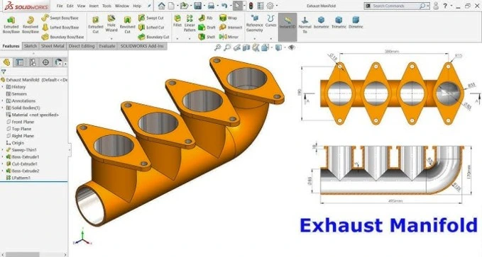
GD&T works in a very clear way. The whole process starts with the creation of the design. You know, designers use software to make 3D models. And, during this phase, they take the assistance of GD&T. They make sure each and every detail meets the required specifications. They check out if the size, place, and tolerance meet the standard.
After adding the GD&T callout, the model is not just a model; it is a complete instruction set for production. At this point, datums are selected carefully; it is very critical. They will act as reference points, surfaces, or axes to measure all other features accurately. This is the key step that will define the functional assemblies.

Basically, GD&T defines how much variation is acceptable from the reference. This compromising range will not compromise the fit, quality, and functionality of the part. If the right tolerance is applied, the part will not be over-machined nor loose. It saves your time and helps reduce waste.
After production, GD&T is used to inspect the quality of the final workpiece. Different type sof tools are used for this purpose, for example, CMM machines, laser scanners, and callipers. After all these steps, GD&T still helps. It helps in communication between designers, engineers, and manufacturers.
Common Mistakes & Best Practices
You know, even ecpeirced engineer can make mistakes. But if you know what those mistakes are and how you can avoid them, there will be minimal chances of errors. Have a look;
Common Mistakes
- Overcomplicated drawings: Stuffing too many symbols and unnecessary tolerance can be confusing for manufacturers. It can slow down the production.
- Wrong selection of datum: You know, choosing the right reference is necessary; it will ruin the whole game.
- Ignoring function requirements: Some people only focus on the looks of the part, but the performance matters the most. So, apply geometric tolearnce pcarefully.

Best Practices:
- Don’t complicate the thing: Try to use on;y necessary symbols. Don’t stuff the things. Otherwise, it will become difficult to understand.
- Choose datum wisely: Datums decide what the dimensions of the final part will be. Therefore, select wisely.
- Communicate with your team: To confirm the tolerances and make them achievable and practical, communicate with manufacturing and quality teams during design.
Well, by avoiding the above-described mistakes and following the best practices, you can make quality parts, reduce rework, and boost the efficiency of our work. So, we can say that there are unlimited benefits of GD&T if you follow the rules properly.
Summary and Conclusion
Alright! We can conclude from the above discussion that for the creation of precise and accurate parts, GD&T is vital in modern manufacturing. It will help decide tolerance, shape, size, and position. Moreover, it assists in communication between the team. Ultimately, it helps reduce errors and saves time and money.