- Heim
- Ressourcen
- Daten
- G-Code Command Reference Table
G-Code Command Reference Table
- Von: HDCMFG
Facebook
Youtube
BIKE24 nutzt für den genannten Dienst die technische Plattform von Instagram (Facebook Ireland Ltd., 4 Grand Canal Square, Dublin 2, Ireland bzw. Instagram Inc., 1601 Willow Road, Menlo Park, CA, 94025, USA). Instagram speichert personenbezogene Daten von Ihnen, wenn Sie diese Seite besuchen.
Linkedin
Inhaltsverzeichnis
G-code (Geometric Code) is the universal programming language used to control CNC (Computer Numerical Control) machines. Developed in the 1950s at MIT, G-code remains the backbone of modern CNC machining, enabling precise control over machining processes like milling, turning, and laser cutting.
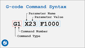
Each G-code command starts with a letter (e.g., G, M, or F) followed by numerical values, directing the machine to:
- Control movement (G-commands): Determine the tool’s path and speed (e.g., moving to coordinates, linear/arc motion).
- Manage functions (M-commands): Handle start/stop actions (e.g., spindle rotation, tool changes, coolant on/off).
While standardized under ISO 6983, variations exist across machine manufacturers (e.g., Fanuc, Haas, Siemens). This table covers 90% of general-purpose G-codes. For advanced functions (5-axis, macros), always consult your machine’s manual for compatibility.
Key Concepts:
- Modal Commands: Remain active until replaced (e.g.,
G01stays in linear motion mode). - Non-Modal Commands: Execute once (e.g.,
G28returns to home position). - Einheiten:
G20(inches) /G21(millimeters). - Coordinate Systems:
G54–G59(work offsets),G90(absolute positioning),G91(incremental positioning). - Sequential Execution: The machine reads code line by line, from top to bottom, No skipping or looping unless using advanced features
G-Code Categories
| Category | Example Commands | Primary Function |
|---|---|---|
| Motion Control | G00, G01, G02, G03 | Tool movement (rapid/linear/arc) |
| Plane Selection | G17, G18, G19 | Select working plane (XY/XZ/YZ) |
| Units & Measurement | G20 (inches), G21 (mm) | Set measurement system |
| Coordinate Systems | G54-G59, G92 | Define work offsets or temporary coordinates |
| Tool Compensation | G40, G41, G42, G43 | Adjust for tool size/length |
| Canned Cycles | G81-G89 | Automated drilling/tapping routines |
| Spindle Control | M03, M04, M05 | Start/stop spindle rotation |
| Coolant Control | M08, M09 | Turn coolant on/off |
| Program Control | M30, M02 | End program/reset machine |
| Special Functions | G28, G53 | Return to home/machine coordinates |
Note: 80% of basic programs use just: G00/G01, G17/G20/G21, M03/M05, und M30.
Common G-Code Command Reference Table
| Command | Funktion | Parameters | Example | Anmerkungen |
|---|---|---|---|---|
| G00 | Rapid Positioning (Non-cutting move) | X, Y, Z (target coordinates) | G00 X10 Y5 Z2 | Avoid collisions; no cutting occurs. |
| G01 | Linear Interpolation (Cutting move) | X, Y, Z, F (feed rate) | G01 X20 Y15 Z0 F150 | Maintain consistent feed rate for surface finish. |
| G02 | Clockwise Circular Interpolation | X, Y, I, J, K (arc center offsets) | G02 X30 Y30 I5 J0 | I/J/K define arc center relative to start point. |
| G03 | Counter-Clockwise Circular Interpolation | Same as G02 | G03 X40 Y20 I0 J-5 | Used for arcs and circles. |
| G17 | XY-Ebenenauswahl | Keiner | G17 | Default plane for most milling operations. |
| G18 | XZ-Ebenenauswahl | Keiner | G18 | Used for lathe operations. |
| G19 | YZ-Ebenenauswahl | Keiner | G19 | Rarely used in standard milling. |
| G20 | Inch Units | Keiner | G20 | Sets all values to inches. |
| G21 | Metrische Einheiten | Keiner | G21 | Sets all values to millimeters. |
| G28 | Return to Home Position | X, Y, Z (optional via intermediate) | G28 X0 Y0 Z0 | Machine moves to reference point. |
| G40 | Cancel Cutter Compensation | Keiner | G40 | Disables tool radius offset. |
| G41 | Left Cutter Compensation | D (tool radius offset number) | G41 D1 | Compensates for tool radius to the left of the path. |
| G42 | Right Cutter Compensation | D (tool radius offset number) | G42 D2 | Compensates for tool radius to the right of the path. |
| G43 | Tool Length Compensation | H (tool height offset number) | G43 H3 | Adjusts for tool length; critical for multi-tool setups. |
| G54 | Work Coordinate System 1 | Keiner | G54 | Selects pre-defined work offset (G54–G59). |
| G80 | Cancel Motion Modes | Keiner | G80 | Cancels cycles (e.g., drilling, tapping). |
| G90 | Absolute Positionierung | Keiner | G90 | All coordinates are relative to origin. |
| G91 | Inkrementelle Positionierung | Keiner | G91 | Coordinates are relative to current position. |
| M03 | Spindle Start (Clockwise) | S (spindle speed) | M03 S2000 | Spindle rotates clockwise at 2000 RPM. |
| M04 | Spindle Start (Counter-Clockwise) | S (spindle speed) | M04 S1500 | Used for reverse cutting operations. |
| M05 | Spindle Stop | Keiner | M05 | Stops spindle after operation. |
| M06 | Tool Change | T (tool number) | M06 T5 | Automatic tool change (requires ATC). |
| M08 | Coolant On | Keiner | M08 | Activates flood coolant. |
| M09 | Coolant Off | Keiner | M09 | Turns off coolant. |
| M30 | Program End & Reset | Keiner | M30 | Ends program and resets machine. |
| F | Feed Rate | Feed value (units/min or units/rev) | F200 | Set in G94 (units/min) or G95 (units/rev). |
| S | Spindle Speed | RPM value | S3000 | Speed depends on material and tool type. |
| T | Werkzeugauswahl | Tool number | T4 | Prepares tool for M06 command. |
FAQ
No. Modern CAM software generates most code automatically. Focus on understanding common commands like G00, G01, M03, und M30.
Basics are universal, but advanced features vary by brand. For example:
- Haas: G187 (high-speed mode)
- Fanuc: G05.1 (smoothing)
Always check your machine’s manual for specifics.
Yes. For examples:
Benutzen G00 (rapid move) instead of G01 (slow cut) → Tool crashes into the workpiece.
Forgetting M05 (spindle stop) → Spinner keeps rotating after the program ends.
- Test first: Run programs in "dry run" mode (no cutting).
- Single-block mode: Execute one line at a time to catch errors.
- Backup settings: Note down machine offsets before editing.
- Clean workspace: Remove debris that could interfere with motion.
Yes, but only tweak values you fully understand and never modify tool paths without CAM software – small errors can cause crashes.
CAM programs: Fusion 360, Mastercam, SolidWorks CAM (paid), FreeCAD, Easel (web-based).
Note: Avoid writing code from scratch unless you’re experienced.
Ressourcen
- LinuxCNC G-Code Documentation
- Fanuc 30i/31i/32i Series Programming Manual
- Siemens 840D SL Advanced Programming Guide
- ISO 6983-1 Standard
- Haas Mill Programming Workbook
- Mazak SmoothX CNC Programming Manual
- G-Code Basics (NRAO)
- CNC Cookbook Blog
- NC Viewer (Web, Free)
- CAMotics (Open-source)
- Vericut
- Practical Machinist
- LinuxCNC Forum
- Stack Exchange – Manufacturing
- Reddit r/CNC